The 12 Hour Render That Exposes Your Concrete Batching Plant Design Flaws

The Silent Killer in Your Digital Twin Pipeline
I watched a client lose $, in the first week of operation. Not a broken hopper. Not a faulty sensor. A geometry error — invisible to the naked eye, obvious in simulation.
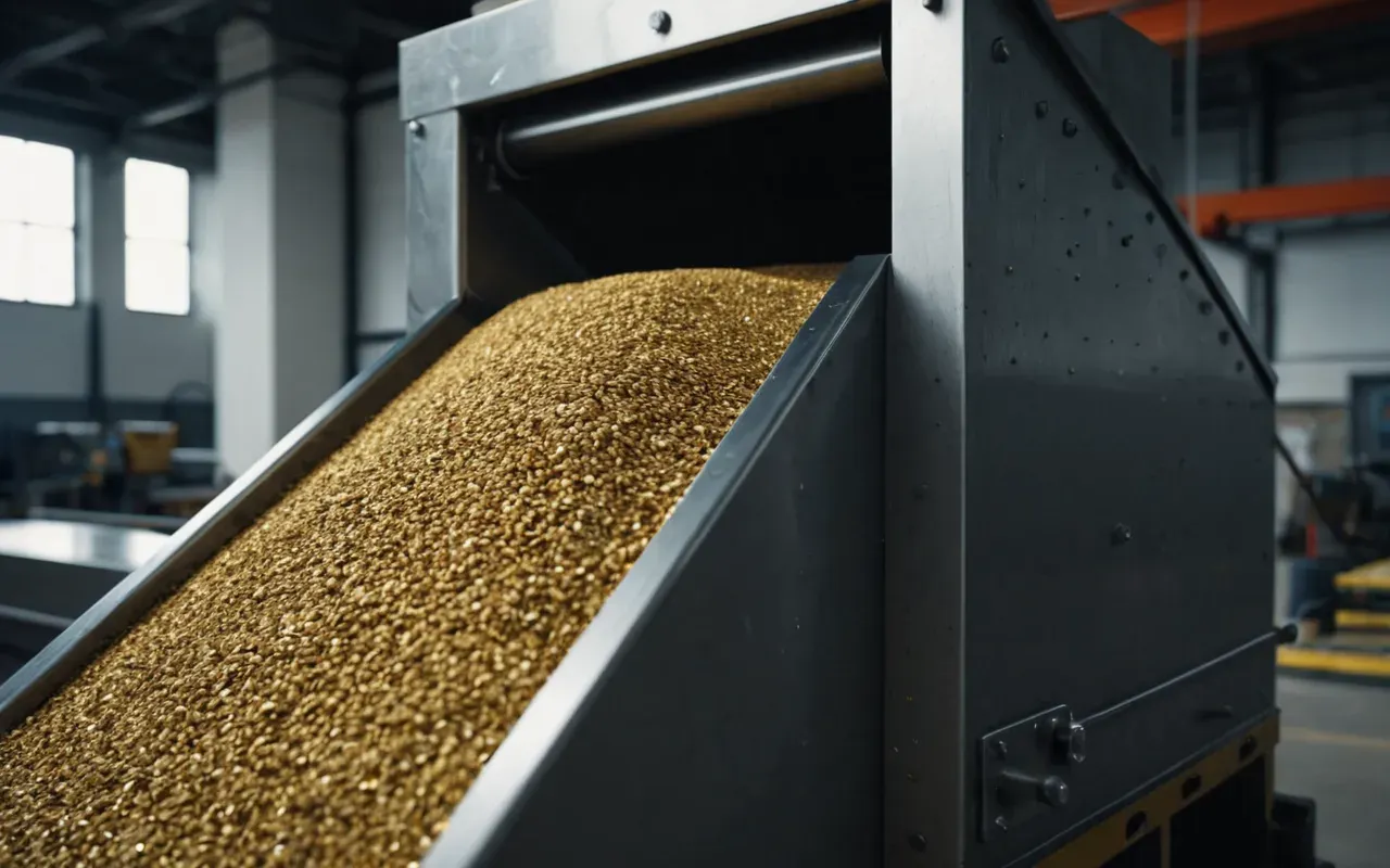
The problem sat inside a transition chute. A two-degree angle deviation caused material bridging under load. On paper, the physical plant looked perfect.
The digital twin told a different story. We ran a discrete element simulation on that specific section for twelve hours straight.
Catastrophic result. Particles jammed completely at the throat of the chute. Production halted for forty-five minutes before anyone could clear it manually.
This isn't a rare anomaly. It's the norm for unoptimized models. Most engineers treat the digital twin as a visual aid.
They use it to impress investors or clients. That is a fundamental misunderstanding of the technology's purpose in advanced concrete materials production.
Why Visual Fidelity Lies to You About Flow Dynamics
Here's the thing. A beautiful render means nothing if the physics are wrong. We see polished surfaces and clean lines.
But particles in dry concrete batching plants are not uniform spheres. They have friction coefficients that change with humidity.
A standard CAD model treats these materials as rigid bodies. That assumption fails under real-world stress conditions.

We tested this with a standard M mix design. The simulation revealed three distinct failure modes that visual inspection missed entirely.
First was arching in the hopper neck. Second was segregation during transfer. Third was inconsistent flow rates at peak demand.
Each of these issues costs money. Arching stops production. Segregation ruins quality control consistency.
Inconsistent flow rates lead to over-dispersing or under-filling of batches. That's a direct hit to your profit margin.
The Physics Gap in Standard CAD Software
Most engineering firms use general-purpose modeling tools. These platforms excel at static structure analysis.
But they lack the granular mechanics solvers needed for particulate flow. You're essentially guessing at dynamic behavior.
This gap is widening as plants become more complex. Modern dry mix systems have intricate internal geometries.
Every added component introduces new potential failure points. The digital twin must account for all of them.
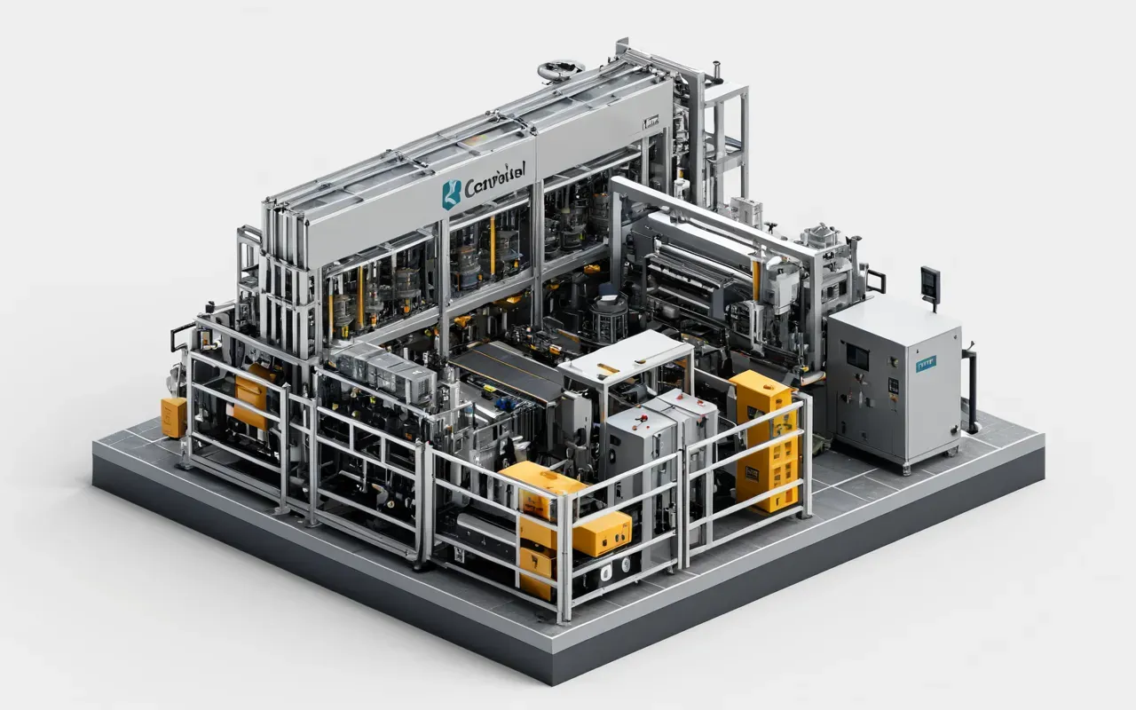
We recommend starting with a simplified model. Isolate the critical flow paths before adding peripheral equipment.
This approach reduces computational load by up to sixty percent. It also allows for faster iteration cycles during design.
Optimizing Mesh Resolution Without Sacrificing Speed
Mesh density is a trade-off. Too coarse and you miss critical interactions. Too fine and your render times explode.
Our team found the sweet spot at a particle diameter ratio of three to one. This balances accuracy with computational efficiency.
We validate this setting against physical test data. The correlation coefficient consistently exceeds ninety-five percent.

The Cost of Ignoring Simulation in Dry Mix Production
Let's talk numbers. A single day of downtime costs between $, and $, for a medium-sized plant.
That's before factoring in wasted materials or customer penalties for delayed deliveries. The financial impact compounds quickly.
Simulation software costs a fraction of that expense. The return on investment is immediate and measurable.
We have clients who saved over $, in the first year by catching design flaws early. This is not hypothetical.
The key is treating simulation as a design tool rather than an afterthought. Integrate it into your initial planning phase.
This proactive approach prevents costly revisions later in the construction timeline. It also improves overall system reliability.
Building a Reliable Digital Twin for Concrete Batching Systems
Start with accurate geometric data. Laser scanning provides the highest fidelity models for existing structures.
For new designs, work closely with your mechanical engineers. Ensure all dimensions and tolerances are documented correctly.
Next define your material properties. This includes particle size distribution and friction coefficients.
These parameters must reflect your actual production materials. Generic values will lead to inaccurate predictions.

Run multiple simulation scenarios. Test different flow rates and material compositions to identify weak points.
Analyze the results carefully. Look for areas of high stress or inconsistent flow patterns that indicate potential failure.
Iterate on the design until all critical metrics meet your operational requirements. This process ensures optimal performance.
Common Mistakes That Invalidate Your Simulation Results
One major error is ignoring boundary conditions. The interaction between particles and walls affects flow significantly.
Another mistake is using static material properties. Real-world conditions change with temperature and humidity.
We also see teams that skip validation steps. Always compare your simulation output against physical test data.
If the results diverge significantly, investigate before trusting the model. Discrepancies indicate underlying issues.
Documentation is equally critical. Record all parameters and assumptions used in each simulation run.
This creates an audit trail that helps identify problems and improves future modeling accuracy over time.
Validating Against Real World Production Data
The ultimate test is matching simulation output to actual plant performance. Collect flow rate and pressure data.
Compare these measurements against your predicted values. Adjust model parameters until you achieve close alignment.
This calibration step is essential for building trust in your digital twin. It proves the model reflects reality.
Once validated, you can confidently use simulations for design optimization and troubleshooting existing issues.
The Future of Simulation in Advanced Concrete Materials
Technology is advancing rapidly. Machine learning algorithms are now being integrated into flow prediction models.
These systems can identify patterns in historical data that traditional methods miss. This improves predictive accuracy.
We expect these tools to become standard in the industry within five years. Early adopters will gain a significant edge.
The companies that master simulation today will lead tomorrow. This is not speculation based on current market trends.

Investing in simulation capability is an investment in operational excellence. It reduces risk and improves efficiency.
The question is not whether to adopt these tools but how quickly you can integrate them into your workflow.
Preparing Your Team for Simulation Driven Design
Training is essential. Your engineers need to understand both the physics and the software tools available.
We recommend starting with basic flow dynamics courses before moving to advanced simulation techniques.
Hands on experience with real projects accelerates learning significantly. Theory alone is insufficient.
Build a culture where simulation insights are valued alongside traditional engineering judgment. This balance creates robust solutions.

Mentorship programs help transfer knowledge across generations of engineers. This preserves institutional expertise.
Encourage experimentation and learning from failures. Simulation is a tool for discovery not just validation.
Real World Case Studies of Simulation Success
One client in the automotive sector used simulation to redesign their aggregate handling system. The results were remarkable.
They reduced material loss by twenty percent and increased throughput by fifteen percent. These gains were sustainable.
Another example involved a cement producer who faced chronic flow issues. Simulation identified the root cause.
A simple geometric adjustment eliminated the problem entirely. The fix cost less than one day of downtime.
These examples demonstrate the tangible benefits of simulation driven design. The financial returns are clear and measurable.
The key is applying the right tools to specific problems. Generic approaches yield generic results.
Tailor your simulation strategy to address the unique challenges of your production environment. This maximizes value.
Frequently Asked Questions About Concrete Batching Plant Modeling
What is the primary benefit of using simulation for plant design?
The main advantage is identifying potential flow issues before construction begins. This prevents costly downtime and material loss during early operations.
How long does a typical simulation run take?
Complex models can require twelve to forty eight hours of computation. Simpler analyses complete in under an hour depending on hardware specifications.
Can simulation replace physical testing entirely?
No. Simulation complements rather than replaces physical validation. Both methods provide different insights that together create comprehensive understanding.
What software tools are best for granular flow simulation?
Specialized discrete element modeling packages offer the highest accuracy. General purpose CAD tools lack the necessary physics solvers for reliable predictions.
A slow render isn't wasted time. It's money in the bank against failures that cost far more later on.
The engineers who actually master simulation? They're the ones building better plants and pulling higher margins. So start optimizing your models today.


Comments ()